Assembly and Fixturing
Expect assembly of this board to be difficult. There are many components, and on both sides of the board, down to 0201 passives. There is little room to support the board for stenciling the second side, and special considerations should be taken for support during second side reflow as well.
Support during stenciling
There are 3d-printable fixtures available for supporting the board during stencil for both sides. They are created in OpenSCAD, so you can load these files and export them as STL or another format as required for your 3D printer.
There is a first side / back stencil fixture available, if you don’t have any 1.2mm boards to support the board during first side stencil.
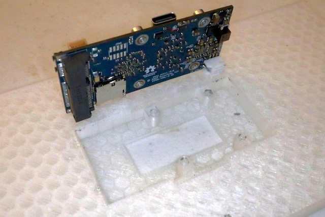
The second side / front stencil fixture uses the the mPCIe connector to support the board on one side, and the mounting holes on the sides and near the other end.
Support during reflow
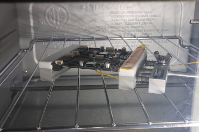
In second-sided reflow, holding the board in a stickvice with PTFE jaws works well:
v0.9 Hardware Errata (rework items)
As v0.9 boards are early-run, there are a few items that need to be fixed up. Some of these items are fixed in software or in updated versions of the BoM, but there are a couple minor cut-and-jumps that will have to be performed.
See the v0.9 errata GitHub issue for the most up-to-date information.